SECTION 4
PARTS REPLACEMENT
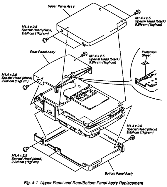
- Remove the six screws (M1.4x2.5 Special Head/black) securing the Upper Panel and Rear Panel
Ass'y. They are taken away. (Refer to Fig. 4-1)
- Remove the five screws (M1.4x2.5 Special Head/black) securing the Bottom Panel Ass'y. It is
taken away. (Refer to Fig. 4-1)
Note: When installing, secure it with torque force of 9.8N·cm (1kgf·cm).
Note: When replacing the Rear Panel Ass'y, be sure to attach the protection sheet (Terminal).
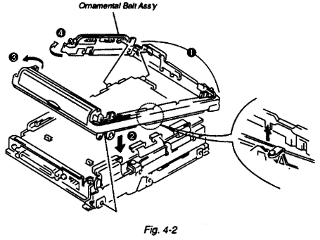
- Spread out Ornamental Belt Ass'y and dislocated it from the frame. (Refer to Fig. 4-2)
Note: When Installing, follow next steps.
 Carefully attach front portion to the unit so that OPEN switch knob
is located in proper position and works smoothly.
 Slide in left, portion to the unit so that a hook on the left side is
fit to the frame.
 During spread out rear portion, attach it.
 Attach right portion so that POWER OFF and AVLS switches knob are
located in proper position and works smoothly.
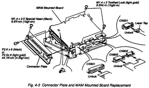
- Remove the two screws (P2.6x6/black or P2.5x6/light gold) and two screws (M1.4x2.5
Special Head/black) securing the Connector Plate to the MAM Mounted Board. (Refer to Fig. 4-3)
Note: When installing, secure screw (P2.6x6/black or P2.5x6 light gold) with torque force
of 44.1N·cm (4.5kgf·cm) and screw (M1.4x2.5 Special Head/black) with torque force
of 9.8N·cm (1kgf·cm).
Note: When the MAM Mounted Board is replaced with new one, perform the program downloading
in accordance with 5-8 before the adjustment.
- Disconnect the flexible cable from the CN501 connector (for Optical ass'y).
Note: When disconnecting (connecting) from (to) CN501 connector, make a solder bridge on the
laser tap of the flexible board, as the laser diode in the optical pickup is easily damaged by
static electricity.
- Unlock the CN801, CN802 and CN803 as shown in Fig. 4-3 and disconnect all the flexible
cables (CN801 for DC-DC converter, CN802 for REC mounted board ass'y, CN803 for mech con mounted
board ass'y)
- Remove the four screws (M1.4x2 Toothed Lock/light gold) securing the MAM Mounted Board to the
frame. (Refer to Fig. 4-3)
Note: When installing, secure it with torque force of 9.8N·cm (1kgf·cm).
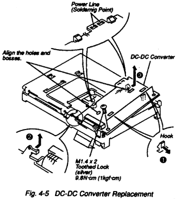
- Remove the two screws (M1.4x2 Toothed Lock/silver) securing the DC-DC Converter to the
Battery Case Ass'y. (Refer to Fig. 4-5)
- Desolder the power line connected the Battery Case Ass'y on the DC-DC Converter. They can be
separated from each other. (Refer to Fig. 4-5)
Note: When installing, secure it with torque force of 9.8N·cm (1kgf·cm).
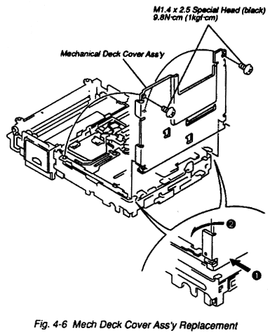
Note: After the removal of the Mech Deck Cover Ass'y, do not apply excessive force to the
Head arm or Head own because Head arm is easily damaged.
- Remove the two screws (M1.4x2.5 Special Head/black) securing the Mech Deck Cover Ass'y and then
stand up the Mech Deck Cover Ass'y vertically and pull it forward toward you. (Refer to Fig. 4-6)
Note: When installing, secure it with torque force of 9.8N·cm (1kgf·cm).
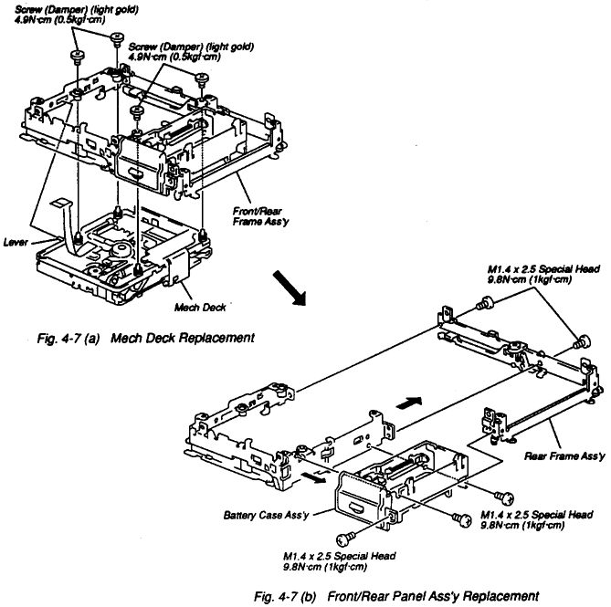
- Remove the four screws (damper/light gold) securing the Front/Rear Frame Ass'y and take out
Mech Deck. (Refer to Fig. 4-7(a))
Note: When installing, secure it with torque force of 4.9N·cm (0.5kgf·cm).
Note: Push the lever on the Mech Deck and dislocate it from the opening on the Front Frame
Ass'y. At the same time take out the Mech Deck.
- Remove the three screws (M1.4x2.5 Special Head/black) securing the Rear Frame Ass'y
and take out Front Frame Ass'y. (Refer to Fig. 4-7(b))
Note: When installing, match the two bosses on the Front Frame Ass'y to two openings on the
Rear Frame Ass'y.
Note: When installing, secure it with torque force of 9.8N·cm (1kgf·cm).
- Remove the two screws (M1.4x2.5 Special Head/black) securing the Battery Case Ass'y.
(Refer to Fig. 4-7(b))
Note: When installing, secure it with torque force of 9.8N·cm (1kgf·cm).
 Note: Through the removal (installtion) of Mech Deck, we recommend it to put on Mech Deck
Base (J-905-914-0A).
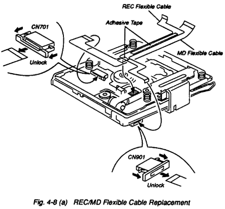
- Disconnect the REC Flexible Cable from CN901 connector (for REC mounted board) and then
carefully peel it off from MD Flexible Cable. (Refer to 4-8(a))
Note: When installing, peel off the paper on the MD Flexible Cable. Attach REC Flexible
Cable on the MD Flexible Cable.
- Disconnect the MD Flexible Cable from CN901 connector (for Mech Con mounted board)
and then peel off the MD Flexible Cable from the Mech Deck. (Refer to 4-8(a))
Note: When installing, peel off the paper on the MD Flexible Cable. Attach REC Flexible
Cable on the Sled Motor Block Ass'y.
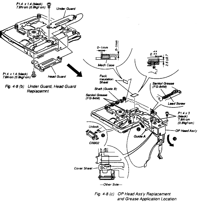
Note: Through the installation (removal) of OP Head Ass'y, do not apply excessive force to
the Head arm or Head own because Head arm is easily damaged.
Note: When the OP Head Ass'y replaced with new one, certainly attach the Cover Sheet and
Pack Insulation Sheet as shown in Fig. 4-8(c).
- Remove the screw (P1.4x1.4/black) securing the head guard and remove the screw (P1.4x1.4/black)
securing the under guard. They can be taken away. (Refer to Fig. 4-8(b))
Note: When installing, secure it with torque force of 7.8N·cm (0.8kgf·cm).
- Disconnect the flexible cable from CN902 connector (for REC mounted board).
- Remove the two screws (P1.4x3/black) securing the shaft (guide A) and remove the OP Head Ass'y
backwards while lifting head arm. (Refer to Fig. 4-8(c))
Note: When installing, secure it with torque force of 7.8N·cm (0.8kgf·cm).
Note: Before installing, apply Sankol Grease (FG-84M) to the Lead Screw and the shaft
(guide B). (Refer to Fig. 4-8(c))
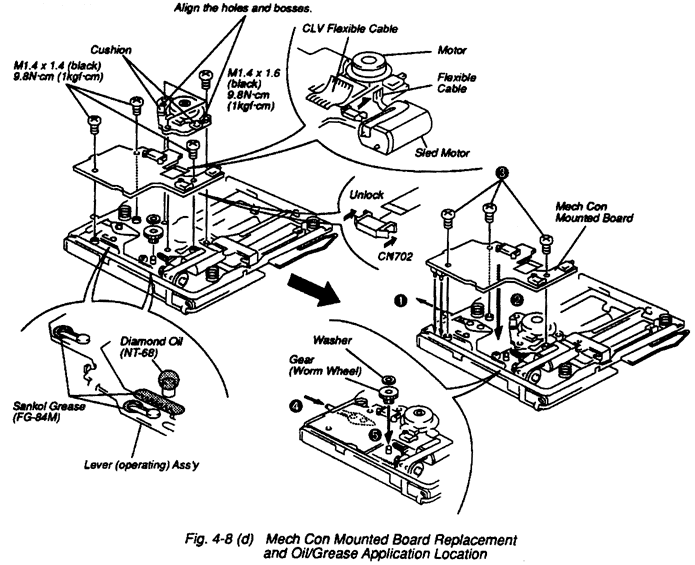
- Remove the Washer from shaft with Tweezers and then pull the Gear (Worm Wheel) up. (Refer to
Fig. 4-8(d))
Note: Before installing, apply Diamond Oil (NT-68) to the chassis. (Refer to Fig. 4-8(d))
Note: When attaching the Gear (Worm Wheel), while pulling the lever direction marked with
arrow 1, install it.
- Disconnect the flexible cable from CN702 connector (for Stepper Motor).
- Desolder CLV flexible cable on the Mech Con Mounted Board and flexible cable of sled motor
with soldering iron.
- Remove the three screws (P1.4x1.4/black) securing the Mech Con Mounted Board and then remove the
Mech Con Mounted Board. (Refer to Fig. 4-8(d))
Note: When installing, secure it with torque force of 9.8N·cm (1kgf·cm).
Note: Before installing, apply Sankol Grease (FG-84M) to the Lever (operating) Ass'y. (Refer
to Fig. 4-8(d))
Note: When installing the Mech Con Mounted Board, while pushing lever direction marked with
arrow 4, install it.
- Remove the three screws (P1.7x1.6/black) securing the Motor and then pull it straight up.
(Refer to Fig. 4-8(d))
Note: When installing, secure it with torque force of 9.8N·cm (1kgf·cm).
Note: When the Motor is replaced with new one, certainly attach the cushion on the Motor.
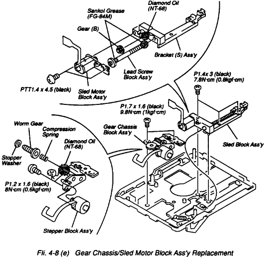
- Remove the two screws (P1.7x1.6/black) securing the Gear Chassis Block Ass'y and then remove the
Gear Chassis Block Ass'y. (Refer to Fig. 4-8(e))
Note: When installing, secure it with torque force of 9.8N·cm (1kgf·cm).
- Remove the Stopper Washer from the shaft with Tweezers and then pull the Worm Gear and
Compression Spring up. (Refer to Fig. 4-8(e))
Note: Before installing, apply Diamond Oil (NT-68) to the shaft of Gear Chassis Block Ass'y.
(Refer to Fig. 4-8(e))
- Remove the two screws (P1.2x1.6/black) securing the Stepper Block Ass'y and then
remove the Stepper Block Ass'y. (Refer to Fig. 4-8(e))
Note: When installing, secure it with torque force of 8N·cm (.6kgf·cm).
- Remove the three screws (P1.4x3/black) securing the Bracket (S) Ass'y and then remove the
Bracket (S) Ass'y. (Refer to Fig. 4-8(e))
Note: When installing, secure it with torque force of 7.8N·cm (0.8kgf·cm).
- Remove the two screws (P1.4x4.5/black) securing the Sled Block Ass'y can be taken away
the Sled Motor Block Ass'y, Lead Screw Block Ass'y, and Gear (B). (Refer to Fig. 4-8(e))
Note: Before installing, apply Diamond Oil (NT-68) to the shaft Bracket (S) Ass'y and apply
Sankol Grease (FG-84M) to the Lead Screw Block Ass'y. (Refer to Fig. 4-8(e))
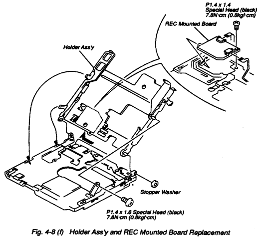
- Remove the screw (M1.4x1.6 Special Head/black) securing the Holder Ass'y. (Refer to Fig. 4-8(f))
Note: When installing, secure it with torque force of 7.8N·cm (0.8kgf·cm).
- Remove the Stopper Washer located right rear of the Mech Deck from the shaft with
Tweezers and then shift it left side and it can be taken away. (Refer to Fig. 4-8(f))
- Remove the screw (M1.4x1.4 Special Head/black) securing the REC Mounted Board Ass'y.
(Refer to Fig. 4-8(f))
Note: When installing, secure it with torque force of 7.8N·cm (0.8kgf·cm).


 Carefully attach front portion to the unit so that OPEN switch knob
is located in proper position and works smoothly.
 Slide in left, portion to the unit so that a hook on the left side is
fit to the frame.
 During spread out rear portion, attach it.
 Attach right portion so that POWER OFF and AVLS switches knob are
located in proper position and works smoothly.


