SECTION 1
INTRODUCTION

1-1 CONFIGURATION OF SERVICE MANUAL

This manual is maintenance guide for model MDH-10 series.
Section 2 describes disc (disk) and tools necessary for maintenance.
Section 3 provides fault diagnostic procedure that may require spare parts, measurement, or adjustment. The overall check (ATP) after part replacement and adjustment will be included in this section.
Section 4 describes how to disassemble / install every part of the unit.
Section 5 describes how to adjust / check the unit after faulty parts replacement, which are found in Section 3.
Section 6 consists of circuit diagrams, assembly drawing, and parts list.
Section 7 describes pin assignment and block diagram of semiconductor.

1-2 CAUTION

Caution:As the laser beam used in the unit is harmful to the eyes, do not attempt to disassemble the enclosure. Refer to servicing to qualified personnel only.

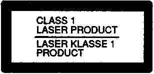
This unit is classified as a CLASS 1 LASER product. The CLASS 1 LASER PRODUCT label is located on the bottom.

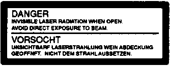
The Danger label is located on the Mechanical Deck Cover Ass'y.

1-3 SWITCHES

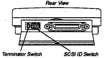
1-3-1 SCSI ID Select

Assign the drive unit's ID number by setting these switches on ON or OFF. Do not assign the same number as one previously assigned to another SCSI device.
ID No.Mark
234
0OFFOFFOFF
1OFFOFFON
2OFFONOFF
3OFFONON
4ONOFFOFF
5ONOFFON
6ONONOFF
7ONONON

1-3-2 Terminator

When the terminator is enabled, the MD DATA drive must be at the last unit in the SCSI chain.

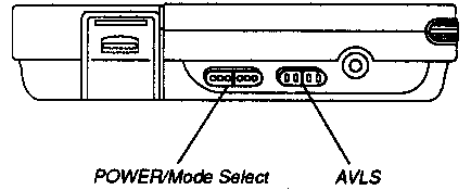
1-3-3 POWER Mode Select

When Reading/Recording data, set this switch to DATA. Also when playback any audio disc, set this switch to AUDIO. POWER Lamp goes on for both settings.

1-3-4 AVLS

When setting this switch to ON. This function allows you to limit the maximum volume without degrading the sound quality.