Sharp MD Portables Power Problems
THE PROBLEM
When the standard mains adaptor bundled with the Sharp portables and OEM equivalents is used in countries that use 110V or 120V mains supply, several users get an error message "POWER?", and the battery will not charge. The battery charging icon does not appear. The unit appears to work otherwise.
The Sharp engineers would seem to have designed the MD machine with a view to protecting the unit from damage caused by too high an input voltage.
An intrepid client applied his mind to the problem and has come up with the simple elegant fix that follows.
The Solution
Over to Mike Harris, the intrepid client, Engineer and Elegant Fixer.
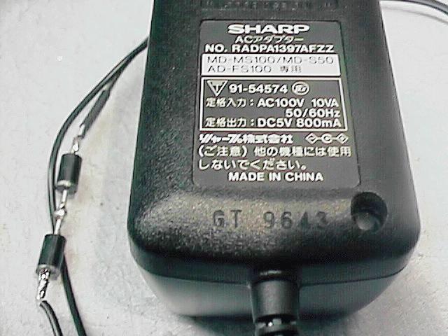
The root of the problem is that the transformer is designed for 100V AC and we have 120V AC. This results in an output voltage of 6V rather than the design target of 5V. The problem could be fixed by either reducing the 120VAC to 100VAC (which is what a step-down transformer does) or to reduce the 6V to 5V after it has been converted to DC. The adaptor transformer is a generic solution that will work with all devices and is the best commercially available solution. However...
THE ROAD LESS TRAVELED:
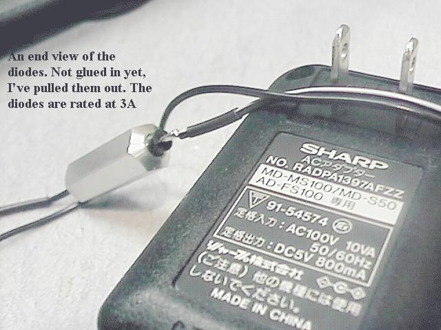
I have chosen to just drop the 6V to 5V because the components are much less expensive. To "drop" 1V, the easiest solution is to just add 2 diodes (forward biased) in line with the 6V. As a quick review, a silicon diode will "drop" between 0.5 and 1V (depending on the type) during use. This is a fixed drop nearly regardless of voltage and current. Diodes also operate from -55c to 150C and are VERY rugged. Just the thing for our project. The only concern that I had was that the power being burned up by the diodes was about 1/2 watt each so they will get pretty warm. I didn't want to leave the bare diodes exposed because being as small as they are, they might burn a hand, or melt a wire. Using a simple heat sink to spread the thermal energy out little will reduce this problem.
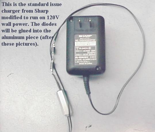
THE CHARGER FIX:
The steps I used to fixed my charger were:
1) Prepare a heat sink for the diodes
2) Cut 1 wire about 10" from the wall plug end.
3) Thread on the heat sink, heat shrink tubing
4) Solder in the diode pair
5) Shrink the heat shrink tubing
6) Coat the resistors in Epoxy
7) Slide the heat sink over the diodes.
8) Quick check for any problems.
9) Let cure overnight. (The epoxy seals the diodes inside the heat sink)
When the MS200 charges, the heat sink is about the same temperature as the charger. (another MD enthusiast, Daniel Kao, mentioned that when he plugged in the charger directly to the wall that it got VERY hot). With this fix in place, it shouldn't get too hot, and mine does not. Without the fix, the transformer is putting out extra current (most likely) and that generates the heat. Heat work by the law of current squared so the extra heat is not just linear, but exponential with current.
THE DETAILS:
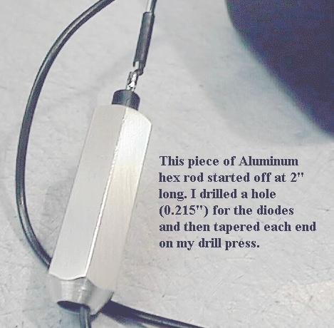
Heatsink : I made a heatsink from a piece of 3/8" hex aluminum, 1.25 inches long. I measured the diameter of the diodes and then drilled a hole into the aluminum so I could insert the diode pair. Smooth all the edges with sandpaper when done. Round or square aluminum could be used as well, I just happen to have some scrap hex rod handy.
Diodes : I purchased some 3 Amp rated diodes (MS200 uses a max of .8 Amp) to make sure we didn't risk the ratings. I used the a pair of 1N5402, however any of the 5400 series will work well. (1N5400-5408) I made sure that I purchased cylindrical shaped diodes (as opposed to the ball shaped) so that I could glue them in my heat sink with out them wanting to turn. The 5400 series is available in both shapes. I purchased the diodes at Radio Shack, 3 for $1.50.
Diodes in Series: Diodes come with a white band on one end. 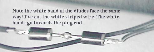 To
put 2 diodes in series, (Diode A and Diode B) solder the banded end of
Diode A to the un-banded end of diode B.
To
put 2 diodes in series, (Diode A and Diode B) solder the banded end of
Diode A to the un-banded end of diode B.
Cutting the transformer Line: It MAKES a difference which way you put the diodes in the cord.
If you cut the:
- White striped wire - then the un-banded end of diode A must be attached to the transformer end of the wire, this leaves the banded end of diode B pointing towards the cord.
- Black Wire - then the banded end of diode B must be attached to the transformer end of the wire, this leaves the un-banded end of diode A pointing towards the cord.

IF MIKE HARRIS WERE KING:
I didn't like cutting the cord on the transformer, I suspect that this voids the warranty on the thing. (It does! Editor.)It also makes for a fairly messy solution for folks not too comfortable with doing this. What I had in mind was to make an adaptor that had a receptacle on one end, about 2 ft of line and a plug on the other end. The diode pair would be in between. There would be no cutting of the wire, just plug the adaptor in line and charge. The problem is that I have not been able to find the receptacles. I've checked with Newark, DigiKey and Switchcraft. The connector is too new apparantly. Of all places, Radio Shack has the plugs, but no receptacles. I called their wharehouse and they couldn't even find the plug in their database!
I'm still looking for receptacles, if anyone knows a source, I'm all ears.
The plug description is: EIAJ2 type, 4.0mm x 1.7mm, DC low power plug.
Author: M P Harris [email protected] (972)995-0273 voice (972)995-2243
fax
Editor: N C Boyde [email protected]
© Copyright 1997 1998 M P Harris, N C Boyde